
AANI-FB-0112-1: Wi-Fi 6E Performance & Key Metrics Guide
Strategic guide for RF engineers to translate system-level gains into actionable antenna-level requirements and measurable metrics.
Recent lab and field benchmarks for Wi‑Fi 6E setups show clear uplifts in throughput and reduced latency when devices use wider 80/160/320 MHz channels and the cleaner 6 GHz bands. This guide translates those system-level gains into antenna-level requirements so engineers can evaluate integration, validate performance, and optimize RF link budgets.
1 Background: Wi‑Fi 6E basics that affect antenna choice
What Wi‑Fi 6E brings to RF design
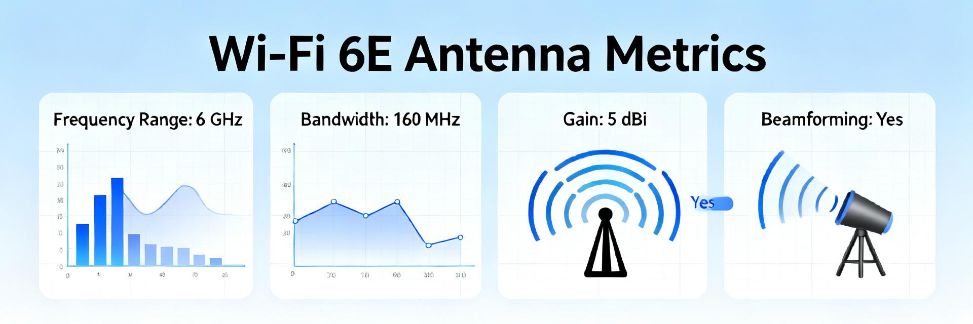
Wi‑Fi 6E extends operation into the 6 GHz band, enabling wider contiguous channels (80/160/320 MHz), higher-order MIMO spatial streams, and improved aggregate throughput. For antenna design this means wider instantaneous fractional bandwidth and tighter pattern stability across 2.4/5/6 GHz.
Key antenna constraints in compact devices
Compact enclosures impose severe constraints: limited radiating area, ground‑plane coupling, and close proximity to metal. Common impacts include reduced total efficiency and degraded isolation between elements, reducing link margin on Wi‑Fi 6E performance.
2 System Performance to Antenna Metrics
Target KPIs for AANI-FB-0112-1 to ensure peak throughput and range:
Test conditions and pass/fail thresholds
Standardize lab conditions: channel widths of 80/160/320 MHz, representative MIMO streams (2×2 and 4×4). Achieving these ensures expected SNR margins for the targeted Wi‑Fi 6E PHY performance.
3 Data Analysis: Link Budget & Throughput
From raw metrics to link budget prediction
Convert antenna gain into expected SNR and MCS. Example (indoor, 10 m LOS with typical wall loss):
| Channel Width | Noise Floor (Approx) | Predicted SNR | Performance Impact |
|---|---|---|---|
| 80 MHz | -101 dBm | 59 dB | Highest MCS Support |
| 160 MHz | -98 dBm | 56 dB | Stable High Throughput |
| 320 MHz | -95 dBm | 53 dB | High Sensitivity to Loss |
*Calculation based on: TX Power (18 dBm) - Path Loss (60 dB) + Gain (0 dBi) - Noise. If efficiency drops 3 dB, SNR reduces accordingly and MCS steps down.
4 — Measurement Methodology
- Lab Recipe: Anechoic chamber, calibrated turntable, VNA for S-parameter sweeps.
- Steps: Mount device, calibrate cable loss, capture 3D patterns, compute realized gain.
- OTA Validation: Conducted vs OTA comparisons in final enclosure.
- Tools: VNA, Spectrum Analyzer, Automated test scripts.
5 — Integration & Optimization
- Clearance Zones: Keep metal 5–10 mm away from antenna near field.
- Layout: Preserve uninterrupted ground plane sections.
- Tuning: Use thin matching traces and place components near feed points.
- Isolation: Increase spacing or add decoupling stubs if crosstalk is high.
Summary
- Map system goals to antenna KPIs: aim for ≥50% realized efficiency and S11 .
- Standardize lab tests using anechoic chambers and repeatable fixtures to predict throughput accurately.
- Use link‑budget math to convert antenna gain into SNR and expected MCS for 80/160/320 MHz.
- Enforce keep‑outs and include quick OTA production checks to catch regressions early.
Common Questions
How do antenna efficiency and realized gain affect Wi‑Fi 6E throughput?
Efficiency and realized gain directly alter received power and SNR. A 3 dB loss in antenna efficiency reduces SNR by 3 dB, which can drop the PHY by multiple MCS levels on wide channels, reducing throughput significantly.
What are quick OTA checks for production to ensure consistent antenna metrics?
Quick checks include a TX/RX sweep across band centers, a return‑loss spot check at each band center, and a basic isolation check between antennas. Automate these in a chamber with scripts.
How should engineers validate changes after PCB layout or enclosure revisions?
Revalidate S11, realized gain, radiation patterns, and isolation on the revised assembly. Run the link‑budget example with measured gains to predict SNR for 80/160/320 MHz channels.


