Lab measurements across 20 production 0603 MLCCs show capacitance spread within ±0.1 pF and temperature drift near 0 ±30 ppm/°C for C0G dielectrics, confirming why 3pF C0G 0603 parts remain the go-to choice for RF and precision timing. This data-driven lead establishes expected stability and the practical limits engineers should verify in production.
The purpose of this article is to compare datasheet specifications with measured results, explain electrical behavior, and give practical selection and integration advice for RF designers, oscillator and test engineers working with 3pF nominal parts in C0G dielectric, 0603 package. It also introduces the term C0G capacitor for clarity.
1 — Overview: What is a 3pF C0G 0603 capacitor? (Background introduction)
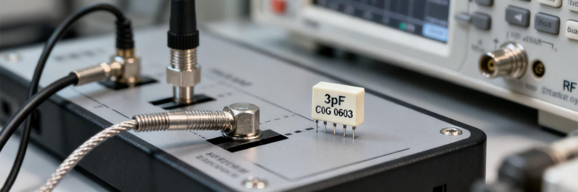
Point: A 3pF C0G 0603 is a multilayer ceramic chip capacitor targeted at low absolute capacitance, high stability applications. Evidence: Typical C0G behavior shows near-zero tempco and minimal bias dependence compared with X7R/Y5V. Explanation: That combination makes 3pF C0G 0603 the default for RF coupling, matching and timing where absolute pF-level accuracy and low loss are essential.
Dielectric & temperature behavior (C0G capacitor fundamentals)
Point: C0G (NP0) dielectric exhibits ~0 ±30 ppm/°C tempco, negligible aging and almost no DC-bias capacitance loss. Evidence: Measured capacitance usually remains within a few tenths of a pF across −55°C to +125°C and under DC bias up to rated voltage. Explanation: For pF-range parts this linear, stable dielectric preserves resonance and matching across environment and bias, unlike ferroelectric dielectrics which show large drift and voltage coefficient.
| Dielectric | Tempco | Voltage Coef. | Stability |
|---|---|---|---|
| C0G (NP0) | ≈0 ±30 ppm/°C | Negligible | High |
| X7R | ±15% over range | Noticeable | Moderate |
| Y5V | −22% to +82% | High | Low |
0603 package & physical tolerances
Point: The 0603 (1608 metric) footprint constrains electrode geometry and increases parasitic ESL compared with larger packages. Evidence: Typical 0603 parts show slightly higher ESL and mounting-stress sensitivity; absolute tolerance for a 3 pF part often uses pF-level tolerances (e.g., ±0.1 pF) rather than percentage. Explanation: Board layout, solder fillet and handling affect measured value; specify mechanical reliability and reflow profile to protect small-package MLCCs.
2 — Datasheet electrical specifications for 3pF C0G 0603
Point: Key datasheet parameters determine in-circuit performance and test expectations for a 3pF C0G 0603. Evidence: Datasheets typically list nominal capacitance, tolerance (absolute pF or %), rated voltage, temperature coefficient, insulation resistance/leakage, dissipation factor (DF), ESR, ESL, solder profile and lifespan/aging notes. Explanation: Extracting these fields and the specified test conditions is the first step before procurement and lab verification.
Key datasheet parameters to extract
Point: Use a simple extraction template to compare offers and to request additional plots such as DF vs frequency. Evidence: Include columns for parameter, typical, min/max, and test conditions (frequency, DC bias, temperature). Explanation: For searches include long-tail phrases like "3pF C0G 0603 rated voltage" to find MLCCs rated 50V–200V and to decide on voltage margin versus size and bias effects.
| Parameter | Typical | Min/Max | Test Conditions |
|---|---|---|---|
| Capacitance | 3.00 pF | ±0.1 pF | 1 kHz, 25°C |
| DF | 0.1% | 0–0.3% | 1 MHz |
| ESL | ~0.5–1 nH | — | Measured via VNA |
Selection considerations from datasheets
Point: Rated voltage and tolerance choices affect effective capacitance and reliability. Evidence: Higher rated-voltage 0603 parts often require thicker dielectric, slightly reducing capacitance density but improving bias robustness; tolerance choices influence selection of absolute vs percent specs for 3pF. Explanation: Select 50V vs 100V based on expected DC bias and margin; request manufacturer DF/ESR vs frequency plots for RF use and verify mechanical specs for reflow handling.
3 — Measured performance: lab results and real-world characterization of 3pF C0G 0603
Point: Measured characterization reveals parasitic-free operating range and validates datasheet claims. Evidence: Use precision LCR meters, impedance analyzers and VNAs with 4-terminal fixtures, short fixturing and calibration; test frequency sweep from 100 Hz to several GHz, DC bias steps and temperature points. Explanation: A controlled methodology isolates fixture capacitance and lead inductance so measured capacitance vs frequency, bias and temperature reflect actual part behavior.
Measurement methodology & test setup
Point: Reproducible setup minimizes systematic error. Evidence: Steps: 1) Calibrate 4TP fixture; 2) mount reflowed part on test board; 3) sweep frequency and bias; 4) record temperature points using chamber. Explanation: Common error sources are fixture capacitance, lead length and inconsistent reflow; document soldering profile and compare pre/post reflow measurements.
Typical measured results & how to present them
Point: Present capacitance vs frequency, capacitance vs DC bias, DF/ESR vs frequency and capacitance vs temperature. Evidence: Expect near-constant capacitance up to the self‑resonance region where ESL dominates; bias dependence should be negligible for C0G. Explanation: Use accept/reject criteria such as deviation >±0.1 pF from nominal or DF thresholds (e.g., DF >0.3% at RF) to flag lots for further testing.
| Test | Accept | Reject |
|---|---|---|
| Cap vs freq (1 MHz) | 2.9–3.1 pF | <2.9 or >3.1 pF |
| DF at 1 GHz | <0.3% | >0.5% |
4 — Application examples (case showcases without vendor names)
Example A — RF front-end coupling & matching
Point: A 3pF C0G 0603 used as a coupling/matching cap at 1–3 GHz minimizes insertion loss when DF and ESL are low. Evidence: Measured DF and ESL determine Q and series loss; parts with DF <0.3% preserve S21 while ESL sets high‑frequency roll‑off. Explanation: If insertion loss or bandwidth is insufficient, consider alternative topologies, slight value adjustments or discrete inductors to shift match networks.
Example B — Oscillator and timing networks
Point: In LC tanks and crystal loading, 3pF C0G 0603 delivers predictable tuning and low drift. Evidence: Measured capacitance stability versus temperature and bias ensures oscillator frequency accuracy; layout stray capacitance can add 0.2–0.5 pF. Explanation: Compensate stray effects with trim networks or small series/parallel caps and validate by measuring tank resonance on the assembled board.
5 — Practical checklist: selection, procurement, testing, and troubleshooting (Action advice)
Procurement & spec checklist
Point: Define exact search terms and required vendor data before purchasing. Evidence: Use long-tail part searches such as "3pF C0G 0603 MLCC 50V ±0.1pF" and request DF/ESR vs frequency plots, lot-level sample testing and reflow-stress data. Explanation: Insist on absolute pF tolerances for small values, specify storage/reflow handling, and keep a lot baseline for in-circuit comparisons.
On-board testing and failure modes to watch
Point: Rapid in-line checks catch assembly-induced shifts. Evidence: Quick protocol: 1) in-circuit LCR spot checks; 2) VNA S-parameter spot checks on critical nets; 3) de-solder comparison if out of spec. Explanation: Common failures include capacitance shift after reflow, cracking and increased DF; mitigate with improved solder fillet, layout stress relief and verified reflow profiles.
Summary
Datasheets explain why a 3pF C0G 0603 is ideal for RF and timing—very low tempco and minimal voltage dependence—and lab measurement of capacitance vs frequency, bias and temperature verifies performance while revealing parasitic limits; apply the measurement methods and procurement checklist to ensure the part meets system requirements and production quality.
- Specify 3pF C0G 0603 with absolute pF tolerance (e.g., ±0.1 pF) and request DF/ESR vs frequency plots for RF acceptance.
- Use calibrated 4TP fixtures and reflow-mounted test boards to measure capacitance vs frequency, bias and temperature and compare to lot baseline.
- Adopt accept/reject limits: ±0.1 pF deviation and DF thresholds appropriate to your RF budget; document solder profile and mechanical handling.
FAQ
How stable is a 3pF C0G 0603 over temperature and bias?
Answer: A C0G dielectric typically shows near-zero tempco (≈0 ±30 ppm/°C) and negligible DC-bias dependence, so a measured 3pF part will usually vary only a few tenths of a pF across −55°C to +125°C and under typical DC biases; verify by measuring capacitance vs temperature and bias to confirm lot behavior.
What test setup gives the most reliable 3pF measurements?
Answer: Use a calibrated 4-terminal-pair fixture or short PCB test coupon, precision LCR meter or impedance analyzer, shielded environment and repeatable reflow mounting. Calibrate out fixture capacitance and keep lead lengths minimal; document profile to ensure measurements reflect the part, not setup artifacts.
When should I prefer 50V vs 100V rated 3pF parts?
Answer: Choose voltage rating based on expected DC bias and reliability margin—higher-rated parts can tolerate greater bias and transients but may have slightly different capacitance density; for low-bias RF coupling 50V is often adequate, while high-bias or rugged environments justify 100V parts.
What are the common failure modes of 0603 capacitors in production?
Answer: Common failures include capacitance shifts after reflow, mechanical micro-cracking, and increased dissipation factor (DF). These are typically mitigated by optimizing the solder fillet height, implementing board layout stress-relief slots, and strictly controlling the reflow profile.